|
|
|---|
| The MRS UAV System 1.5 is being released and this page needs updating. Please, keep in mind that the information on this page might not be valid. |
Pixhawk setup on a new drone
Follow this guide to setup a new drone with the Pixhawk autopilot for the MRS UAV system.
HW setup
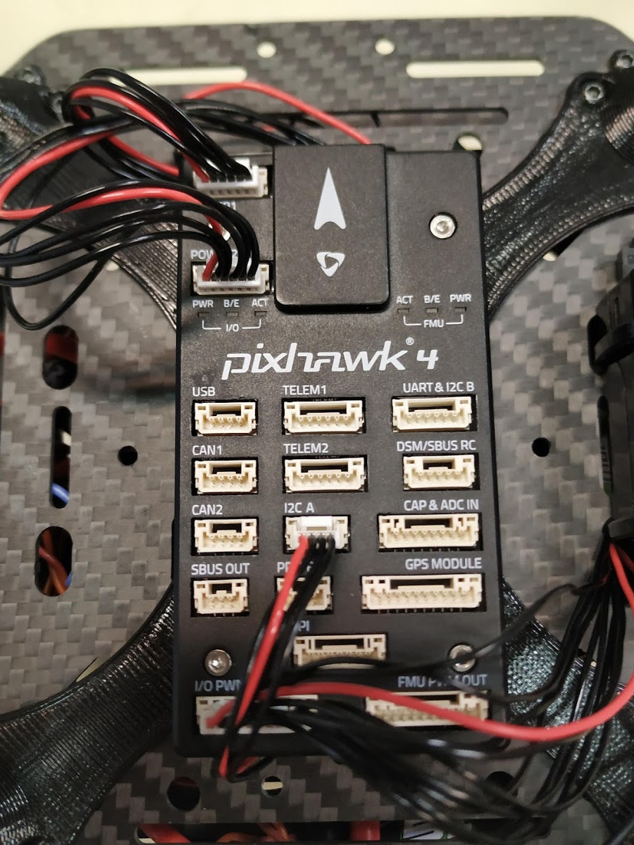
This guide is written for Pixhawk 4, because it is used on most of the MRS aerial platforms. But it is applicable for other versions of the Pixhawk, with minor differences.
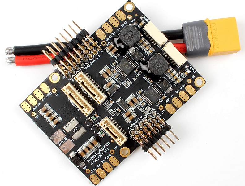
- The Pixhawk 4 comes with a power distribution/supply board. This board provides power distribution for motors (ESCs), connections for ESC signals, two redundant 5V power supplies for Pixhawk and current and voltage monitoring .
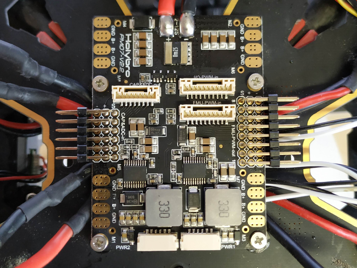
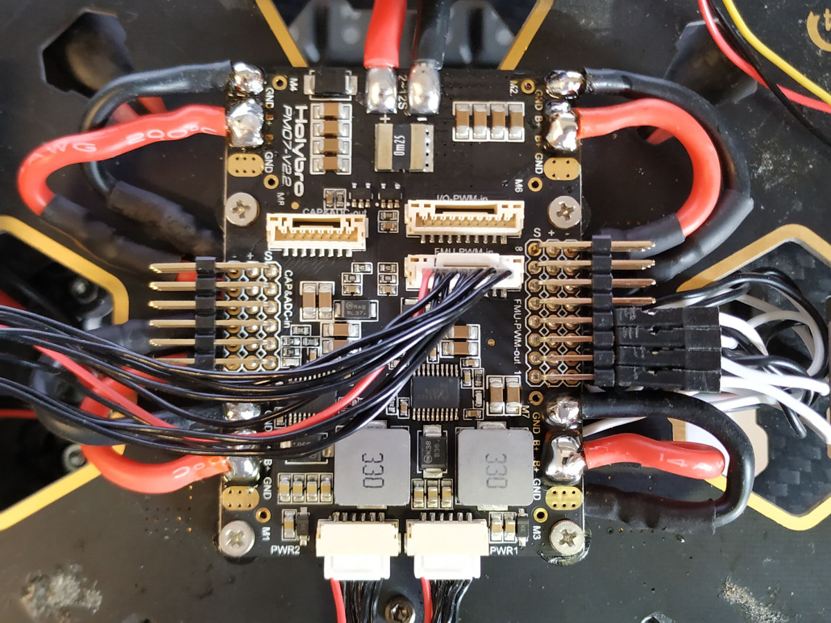
- Install the power board into the frame, solder the motor connections and connect the ESC signal cables.
- You can either solder the ESC signal cables to the M1-M8 ports, or connect them with standard servo cable connectors (servo cable solution is recommended by MRS).
- Connect cables to both power outputs labeled as
PWR1andPWR2. - Connect a cable for the ESC signals to the
IO-PWM-inport (if you soldered the ESC signal cables) or theFMU-PWM-inport (if you used the servo connectors).
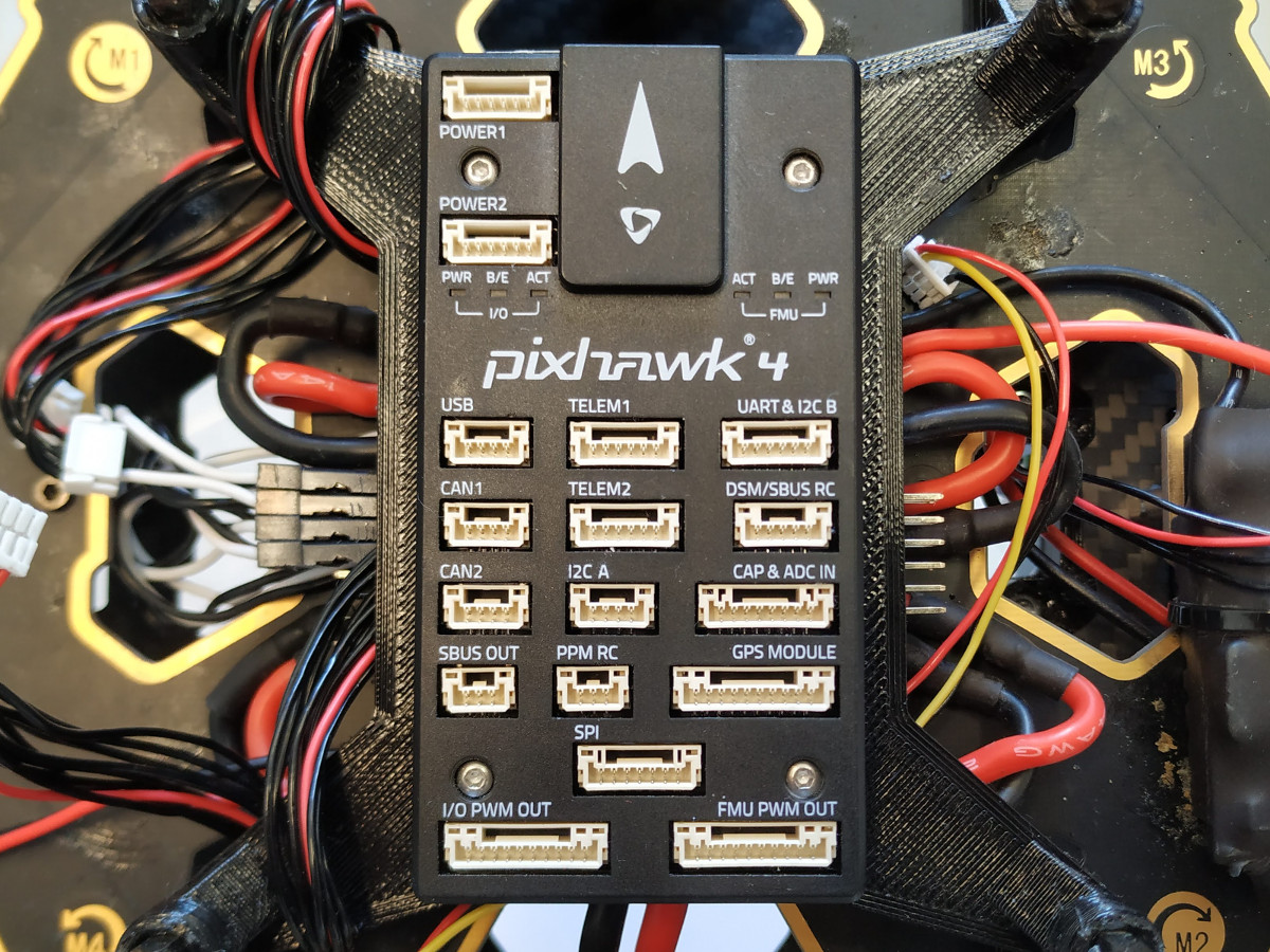
- Install the Pixhawk into the drone frame and connect the power cables from the distribution board to the
POWER1andPOWER2slots. - Connect the ESC signal cable to the
I/O PWM OUTport. - Connect the RC receiver. At MRS we use an OPTIMA SL reciver with SBUS output, so it is connected to the
DSM/SBUS RCport. - Connect the onboard computer to the
TELEM2port. This is a UART port which ensures communication between the Pixhawk and the onboard computer. We use an FTDI serial to USB converter to connect the Pixhawk with the onboard computer. -. Optionally, you can connect other sensors, like a GPS module, rangefinder, etc. Note that the arming button and the buzzer are integrated into the GPS receiver, so if you want to use them either connect the GPS receiver or your own arming button and buzzer to theGPS MODULEport. The arming button has to be disabled in SW if it is not used (this is unsafe).
SD card setup
Pixawk has an SD card for flight logs and for additional configuration. If you want to use the MRS system, you have to use our PX4 sd card configuration. You can find it in the uav_core/miscellaneous repository. Create a folder called etc in the root of the SD card and copy the extras.txt file into this folder. Install the SD card back into the Pixhawk.
SW setup
- Download QGroundControl
- Connect the Pixhawk to your computer with a USB cable and run QGroundControl
- Update the Pixhawk firmware to the latest stable version. Optionally, you can use our tweaked firmware or your custom firmware.
- Set the airframe type according to your drone (most common options are Generic Quadcopter, Generic Hexarotor and Genereic Octocopter)
- Calibrate all the sensors according to the instructions in QGroundControl. Pixhawk has to be installed in the drone frame during calibration.
- Setup your radio. Pair your RC transmitter and your receiver and connect the receiver to the Pixhawk. You should see the RC channel values in QGroundControl. If you do not see the RC channels, check the connection of the receiver.
- Setup the channels on your Transmitter. Proper channel setup is critical for the functionality of the MRS UAV system. 8 RC channels are used:
| Channel | Function | Description |
|---|---|---|
| 1 | Roll | manual control input |
| 2 | Throttle | manual control input |
| 3 | Pitch | manual control input |
| 4 | Yaw | manual control input |
| 5 | Offboard switch | Used to switch the drone in and out of Offboard mode |
| 6 | Flight mode switch | Changes the PX4 flight mode when you fly manually |
| 7 | MRS system switch | Switch used to trigger some functionality of the MRS UAV system, like the “remote” mode |
| 8 | MRS emergency switch | Triggers an emergency behaviour (e-hover, e-land, failsafe land) according to MRS UAV system configuration |
- The following switches are used by default on the RC transmitters:
- If you need to quickly remember what each switch is designated to, you can find it in the RC settings. The MRS team mostly uses Radiomaster TX16s RCs with OpenTX and as you can see from the following screenshot (and the picture of the real thing above), the switches used are
SB,SC,SDandSHrespectively.
- Calibrate your transmitter with the
Calibratebutton in QGroundControl and follow the instruction. - Setup the flight modes. Select Channel 5 as Offboard switch channel and channel 6 as Position Control switch channel and Mode Channel. Set Flight Mode 1 as Manual, Flight Mode 4 as Altitude and Flight Mode 6 as position (3 position switch is used at channel 6 to switch between those three modes).
- Calibrate your ESCs in the
Powersection. You can also configure your battery here (not needed for the MRS UAV system). Note that thePowericon may stay red, you can ignore this. - In the
Safetysection, configure failsafe actions. Standard MRS configuration is Warning for Low Battery Failsafe Trigger, Land mode for RC Loss Failsafe Trigger and Land imediately in the Return To Launch Settings. No other triggers are activated (Object detection, data link loss etc.). - Setup the RC loss failsafe. This failsafe is activated when the drone is flying manually (not in offboard mode) and the RC signal is lost. The RC receiver on the drone is configured to output abnormally low throttle signal when RC is lost, which is detected by the Pixhawk. This guide is for the Hitec Optima receivers, if you are using a different receiver the configuration steps may be different. To configure RC loss failsafe, follow these steps:
- Turn on your RC transmitter and receiver.
- Push you RC transmitter’s throttle stick to the lowest level, then trim the throttle channel all the way down and use sub-trims to trim it even lower (we want to achieve the lowest possible value at the throttle CH2 channel).
- Do not move the other sticks, leave them in centered positions.
- Press the button on the RC receiver until the red LED turns off. Then release the button. The red and blue LEDs will start flashing for a while. This saves the current RC configuration as the output which the RC receiver produces when RC signal is lost.
- In QGroundControl go to the
Parameterssection and set parameterRC_MAP_FAILSAFEtoChannel 2andRC_FAILS_THRto950 us. - Restart the Pixhawk.
- Now when you turn off your RC transmitter, QGroundControl should report
manual control lostand when you turn your RC back on, it should reportmanual control regained.
ROS setup
Once Pixhawk is connected to the computer via the serial to USB, it will show up as /dev/ttyUSB0 (or something similar). Run this command: (replace /dev/ttuUSB0 with your device path)
udevadm info -p $(udevadm info -q path -n /dev/ttyUSB0) | grep 'SERIAL_SHORT\|VENDOR_ID\|MODEL_ID'
You should get something like this:
E: ID_MODEL_ID=6001
E: ID_SERIAL_SHORT=A50285BI
E: ID_VENDOR_ID=0403
Create a new file in /etc/udev/rules.d/ (you will need sudo privileges) and call it 99-usb-serial.rules. Paste this line into the file:
SUBSYSTEM=="tty", ATTRS{idVendor}=="0403", ATTRS{idProduct}=="6001", ATTRS{serial}=="A50285BI", SYMLINK+="pixhawk",OWNER="mrs",MODE="0666"
Replace idVendor, idProduct and serial with you values, and change the OWNER name to your user name. Now, if you disconnect and reconnect the Pixhawk, it should show up as /dev/pixhawk. Now you should be able to run mavros:
roslaunch mrs_uav_general mavros_uav.launch
Garmin rangefinder throught Pixhawk
- The Pixhawk’s sd-card config should contain:
mavlink stream -d /dev/ttyS2 -s DISTANCE_SENSOR -r 100 - Set parameter
SENS_EN_LL40LSto i2c
More info: https://dev.px4.io/master/en/middleware/modules_driver_distance_sensor.html
Configuration
Disabling/Enabling magnetometer
Disable: EKF2_MAG_TYPE := None and SYS_HAS_MAG := 0
Enable: EKF2_MAG_TYPE := Automatic and SYS_HAS_MAG := 1
Magnetometer priorities - FIX for Firmware 1.13.2-3 (Pixhawk 6X/6C)
When flying with external magnetometer, always set the lowest priority to the internal magnetometer and the maximal priority to the external one. Best is to only use the external magnetometer. This prevents jumps in heading odometry and avoids potential crashes as default fusion of both magnetometers was observed to be not reliable.
Publish only the primary magnetometer: SENS_MAG_MODE=Publish primary magnetometer Priorities setting: CAL_MAG0_PRIO := Disabled (internal) and CAL_MAG1_PRIO := Max (external)
